Devices
The plugin creates its devices in 14 groups. Each device has a fixed unit number that never changes, so scripts and dashboards that refer to a unit keep working across updates.
Device names below are the English names. With another language, the names follow that language; a name you changed yourself is always kept.
Overview
| Group | Units | What it covers | Devices |
|---|---|---|---|
| Status | 1 | Working mode | 1 |
| Controls | 10-16 | Modes and setpoints you can change | 7 |
| Power input | 30-32 | Electricity used | 3 |
| Heat output | 40-42 | Heat delivered | 3 |
| Efficiency | 50-52 | COP | 3 |
| Heating circuit | 60-67 | Supply and return, ΔT, pump, flow | 8 |
| Hot water | 80 | Tank temperature | 1 |
| Environment | 90-93 | Outside and room temperatures | 4 |
| Source circuit | 100-106 | Ground loop temperatures, ΔT, pump, flow | 7 |
| Mixing circuits | 120-131 | Mixing circuit 1 and 2 | 4 |
| Compressor | 140-145 | Frequency, capacity, headroom | 6 |
| Refrigerant circuit | 160-174 | Refrigerant temperatures, pressures, diagnostics | 12 |
| Statistics | 180-192 | Run time and starts, totals and per day, week and month | 13 |
| Diagnostics | 200-205 | Faults, cooling release, controller info | 6 |
Two labels are used in the tables:
- Gated: the device only updates while the compressor runs steadily, so idle and start-up readings do not end up in your graphs. See Gated devices.
- Unused: the device is created but not shown until you enable it. See Enabling unused devices.
Status
| Unit | Device | What it shows |
|---|---|---|
| 1 | Working mode | What the heat pump is doing now: Heating, DHW, Swimming pool, EVU (power company lock), Defrost, Heating ext. (external heat source), Cooling, No requirement, or Idle when the compressor uses no power (also with pump power compensation on) |
Controls
These devices change settings on the heat pump. Each write is checked against a fixed list of allowed settings; see Security.
| Unit | Device | What it does |
|---|---|---|
| 10 | Heating mode | Automatic, 2nd heat source, Party, Holidays, Off |
| 11 | Hot water mode | Automatic, 2nd heat source, Party, Holidays, Off |
| 12 | DHW Power Mode | Normal or Luxury |
| 13 | Cooling | Cooling on or off |
| 14 | Temp adjust | Heating curve offset, -5 to +5 °C (unused) |
| 15 | DHW temp target | Hot water setpoint, 30 to 65 °C (unused) |
| 16 | Room temp setpoint | Room temperature setpoint, 15 to 30 °C |
Power input
Electricity used by the heat pump, as kWh meters that also show the current power. With Pump power compensation on, the estimated pump power is included.
| Unit | Device | What it shows |
|---|---|---|
| 30 | Power total | All electricity used |
| 31 | Power heating | Electricity used while heating |
| 32 | Power DHW | Electricity used while heating hot water |
Power total also counts every other mode (cooling, defrost, standby), so it is usually more than heating and DHW added together.
Heat output
Heat delivered, as kWh meters that also show the current heat output.
| Unit | Device | What it shows |
|---|---|---|
| 40 | Heat out total | All heat delivered |
| 41 | Heat out heating | Heat delivered to the heating system |
| 42 | Heat out DHW | Heat delivered to the hot water tank |
Efficiency
COP: heat out divided by power in. All three are gated, and each only updates in its own mode. See COP accuracy for the Domoticz setting that keeps the averages right.
| Unit | Device | What it shows |
|---|---|---|
| 50 | COP total | COP in heating and hot water mode |
| 51 | COP heating | COP in heating mode |
| 52 | COP DHW | COP in hot water mode; lower than heating because the water is hotter |
Heating circuit
| Unit | Device | What it shows |
|---|---|---|
| 60 | Heat supply temp | Water temperature leaving the heat pump |
| 61 | Heat return temp | Water temperature coming back from the heating system |
| 62 | Return temp target | The return temperature the controller aims for (from the heating curve) |
| 63 | Heating ΔT | Supply minus return. Gated, but also updates during passive cooling |
| 64 | Heating ΔT target | The controller's ΔT setpoint (unused) |
| 65 | Heating ΔT actual | The controller's own ΔT reading (unused) |
| 66 | Heating pump | Heating circulation pump (HUP) speed, % |
| 67 | Heating flow | Flow through the heating circuit, l/h (unused) |
Hot water
| Unit | Device | What it shows |
|---|---|---|
| 80 | DHW temp | Hot water tank temperature |
Environment
| Unit | Device | What it shows |
|---|---|---|
| 90 | Outside temp | Outside temperature |
| 91 | Outside temp avg | The controller's averaged outside temperature (unused) |
| 92 | Room temp | Room temperature from the controller's room sensor |
| 93 | Room temp target | The controller's room temperature target (unused) |
Source circuit
The ground loop or well that the heat pump takes its heat from.
| Unit | Device | What it shows |
|---|---|---|
| 100 | Source inlet temp | Brine temperature coming from the ground |
| 101 | Source outlet temp | Brine temperature going back to the ground |
| 102 | Source ΔT | Inlet minus outlet. Gated, but also updates during passive cooling |
| 103 | Source ΔT target | The controller's source ΔT setpoint (unused) |
| 104 | Source ΔT actual | The controller's own source ΔT reading (unused) |
| 105 | Source pump | Brine pump (VBO) speed, % |
| 106 | Source flow | Flow through the source circuit, l/h |
Mixing circuits
Only useful if your installation has mixing circuits; all four start unused.
| Unit | Device | What it shows |
|---|---|---|
| 120 | Circuit 1 temp | Mixing circuit 1 temperature (unused) |
| 121 | Circuit 1 target | Mixing circuit 1 target (unused) |
| 130 | Circuit 2 temp | Mixing circuit 2 temperature (unused) |
| 131 | Circuit 2 target | Mixing circuit 2 target (unused) |
Compressor
| Unit | Device | What it shows |
|---|---|---|
| 140 | Compressor freq | Current compressor speed, Hz |
| 141 | Compressor target freq | The speed the controller asks for (unused) |
| 142 | Compressor min freq | The lowest speed allowed right now (unused) |
| 143 | Compressor max freq | The highest speed allowed right now (unused) |
| 144 | Compressor capacity | Load compared with the maximum, %. Gated |
| 145 | Freq headroom | Target minus actual speed, Hz: how much the compressor can still speed up. Updates whenever the compressor runs |
Refrigerant circuit
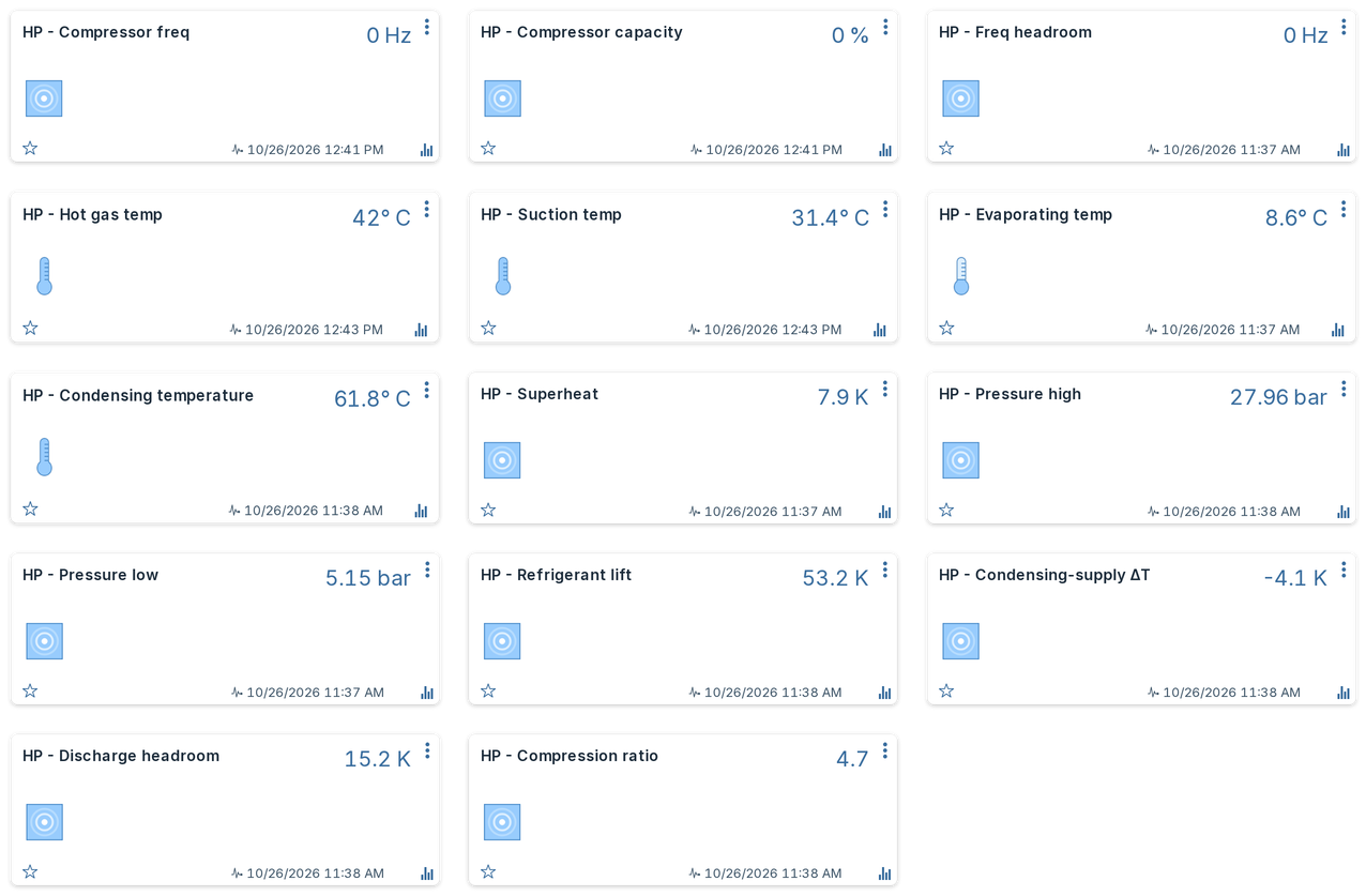
Temperatures and pressures inside the refrigerant circuit, plus derived values that show how healthy the circuit is. The derived values are most useful as trends over weeks and months; a single reading says little.
| Unit | Device | What it shows |
|---|---|---|
| 160 | Hot gas temp | Refrigerant temperature leaving the compressor |
| 161 | Suction temp | Refrigerant temperature entering the compressor |
| 162 | Compressor heating temp | The compressor body heating sensor |
| 163 | Evaporating temp | Temperature at which the refrigerant boils. Gated |
| 164 | Condensing temperature | Temperature at which the refrigerant condenses, as calculated by the controller. Gated |
| 165 | Superheat | How far the gas is above its boiling point at the compressor inlet, K. Gated |
| 166 | Pressure high | High-side pressure, bar. Gated |
| 167 | Pressure low | Low-side pressure, bar. Gated |
| 171 | Refrigerant lift | Condensing minus evaporating temperature, K. Gated |
| 172 | Condensing-supply ΔT | Condensing temperature minus supply water temperature, K. Gated |
| 173 | Discharge headroom | Margin between hot gas temperature and the controller's hot gas limit, K. Gated |
| 174 | Compression ratio | High-side divided by low-side pressure (absolute). Gated |
Reading the diagnostics
Refrigerant lift is the temperature gap the compressor has to bridge, and the main driver of COP: the smaller the lift, the higher the COP. It rises with hotter supply water (hot water mode, a steeper heating curve) and with colder brine. A lift that creeps up over a season at the same outside temperature points at a colder source or a higher supply temperature than needed.
Condensing-supply ΔT can be positive or negative:
- Positive (low-temperature heating): the condenser has headroom. A value that keeps rising at similar conditions can point at fouling or too little water flow.
- Negative (hot water, high supply temperatures): normal; the heat comes mostly from cooling the very hot gas rather than from condensing.
Discharge headroom is how far the hot gas is from the temperature at which the controller stops the compressor. Shrinking headroom over time is a reason to have the heat pump checked before it starts tripping.
Compression ratio rising over months at similar conditions can point at a refrigerant circuit problem, such as a slow leak or a restriction.
Statistics
| Unit | Device | What it shows |
|---|---|---|
| 180 | Compressor hours | Total compressor running hours |
| 181 | Compressor starts | Total compressor starts |
| 182 | Compressor last cycle | Length of the last finished compressor run, minutes. Updates when a run ends; runs shorter than 1 minute are ignored |
| 183 | Heating runtime | Total hours in heating mode (unused) |
| 184 | DHW runtime | Total hours in hot water mode (unused) |
| 185 | Cooling runtime | Total hours in cooling mode (unused) |
| 186 | Compressor run time | Compressor run time per day, week, month and year |
| 187 | Compressor start counter | Compressor starts per day, week, month and year |
| 188 | Heating run time | Run time for space heating per period |
| 189 | Hot water run time | Run time for hot water per period |
| 190 | Backup heater run time | Time the first backup heater (ZWE1) was on, per period |
| 191 | Cooling run time | Time in passive cooling per period (unused) |
| 192 | Heat pump run time | Heat pump operating time per period (unused) |
Hours divided by starts gives the average run length. Many short runs (frequent starts, short last cycles) wear the compressor faster than few long ones.
Run time per day, week and month
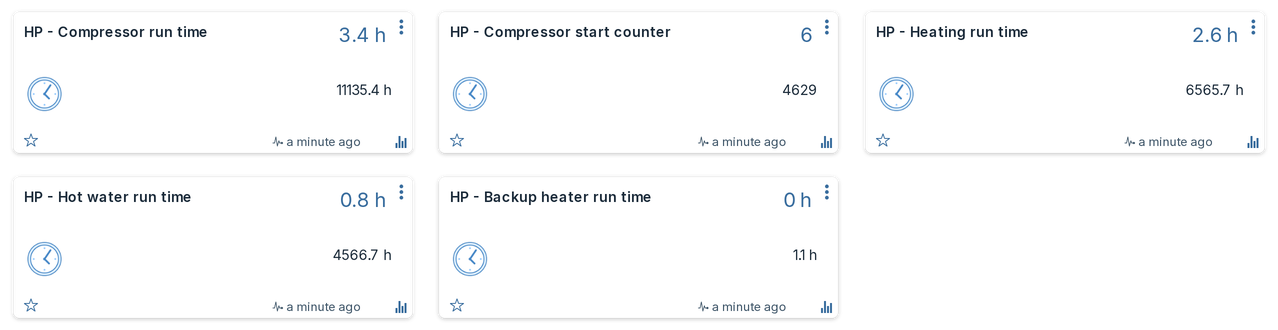
Units 180 to 185 show lifetime totals, which only ever rise. Units 186 to 192 read the same controller totals but are Domoticz counters, so Domoticz works out the periods itself:
- The card shows today's run time (or today's starts) and the lifetime total.
- The device log has bar charts per day, week, month and year, for example how long the hot water ran each day this month, or on which days the backup heater came on.
The run times are shown in minutes ("Today: 84 min"). On a Domoticz version that lets plugins set a counter's divider, the plugin creates them in hours instead ("Today: 1.4 h"). Either way the stored values are the same, so you can switch an existing device yourself: in Setup → Devices, edit the device and set Counter Divider to 60 and Unit to h for hours, or Counter Divider to 1 and Unit to min for minutes. The plugin sets the divider and unit only when it creates the device and never changes them afterwards.
The counters start at the controller's lifetime total, so the first day's history begins when the plugin first created them; earlier days are not filled in.
Diagnostics
| Unit | Device | What it shows |
|---|---|---|
| 200 | Error count | Number of errors stored in the controller (unused) |
| 201 | Cooling permitted | Whether the controller currently allows cooling (unused) |
| 202 | Cooling release | Time left until cooling is allowed, minutes (unused) |
| 203 | Last fault | Newest fault stored in the controller, with its time, for example 790: Severe inverter fault (2022-07-15 13:18). See Fault codes |
| 204 | Firmware | Controller firmware version, for example V3.92.3 (unused) |
| 205 | Heat pump type | Type designation the controller reports, for example MSW2-9S (unused) |
Last fault shows the newest fault the controller has stored, also after it was cleared, and "No faults" when there is none. When the controller stores a new fault, the plugin also writes it to the log as an error and sends one notification through your Domoticz notification systems. A fault that was already there when the plugin first read the controller is not announced.
Gated devices
Gated devices only send a value while the compressor runs at or above the controller's minimum target speed, once it has done so for 2 minutes in a row. During idle, start-up and ramp-up they keep their last value instead of logging misleading readings.
- Heating ΔT (63) and Source ΔT (102) also update during passive cooling, when the pumps run without the compressor and the temperature difference is still meaningful.
- Freq headroom (145) is not settled: it updates as soon as the compressor runs.
- The COP devices have further conditions; see COP accuracy.
Health bars
On Domoticz 2026.4 and newer, some cards show a coloured bar (under the title in the standard theme, along the top edge of the card in Machinon): green is normal, amber is worth a look, red is outside a limit. The bar's position shows where the current value sits. A device only gets a bar when its limits come from the controller itself, the WZSV or Luxtronik manual, or Alpha Innotec; there are no guessed limits.

| Unit | Device | Red | Amber | Green | Source |
|---|---|---|---|---|---|
| 160 | Hot gas temp | from T-HG max | below T-HG max | Your controller's own cut-off (faults 704/714), read live | |
| 60 | Heat supply temp | below 16 °C, and from Vorlauf max | 16 °C up to Vorlauf max | Your controller's flow cut-off, read live; 16 °C is fault 732 in cooling | |
| 80 | DHW temp | above 65 °C | below 50 °C | 50 to 65 °C | Below 50 °C is the legionella growth range; 65 °C is the WZSV maximum with the electric heater |
| 165 | Superheat | below 2 K | from 2 K | Fault 765: superheat below 2 K for 5 minutes | |
| 50-52 | COP | below 1 | from 1 | Below 1 the heat pump does worse than an electric heater | |
| 182 | Compressor last cycle | under 6 min | 6 to 30 min | from 30 min | Alpha Innotec: runs under about 6 minutes cost efficiency, 30 to 60 minutes is uncritical |
What happens:
- The plugin writes the bars at start-up, and again when a controller limit changes, for example when the installer changes T-HG max. It does not rewrite them on every update.
- Your own bars are kept. If you change or remove a bar in the device's edit dialog, the plugin leaves that device's bar alone from then on. A device that already had a bar of yours before this version is not touched either.
- On Domoticz before 2026.4 nothing changes: those versions cannot store a bar set by a plugin.
There are deliberately no bars on the return temperature (during hot water it always runs far above the heating return limit), the brine temperatures (Domoticz draws an axis that crosses 0 °C from its centre, which makes the bar unreadable) and the source flow (the flow sensor reads below the manual's minimum in normal operation).
Enabling unused devices
Devices marked unused are created but hidden, to keep the dashboard tidy. To enable one:
- Go to Setup → Devices.
- Filter on the plugin's hardware name and show unused devices.
- Click the green arrow next to the device and give it a name; it then appears on the dashboard tabs.
The plugin never switches a device back to unused, and an enabled device keeps its history.
Reserved unit numbers
Each group has room for new devices, so a future version can add a device without moving existing ones:
2-9, 17-29, 33-39, 43-49, 53-59, 68-79, 81-89, 94-99, 107-119, 122-129, 132-139, 146-159, 175-179, 186-199, 206-209.
Units 168-170 belonged to devices retired in version 2.1.0 and are not reused.